How NAT Traversal Works (Tailscale)

Translator’s Foreword
This article is a translation of a 2020 English blog post: How NAT Traversal Works.
Imagine this scenario: you have one machine in Beijing and another in Shanghai, both on local area networks (e.g., a desktop at home and a laptop connected to Starbucks Wi-Fi). Both have private IP addresses but can access the public internet. How can these two machines communicate directly?
Since both can access the public internet, the simplest approach is to set up a relay server on the public network: both machines connect to the relay, which forwards traffic bidirectionally. However, this method incurs significant performance overhead, and the relay server can easily become a bottleneck.
Is there a way to enable direct communication between the two machines without a relay?
With some networking and protocol knowledge, you’d realize this is possible. This epic-length article from Tailscale explains this “possibility” in a clear, step-by-step manner. If you fully implement the techniques described, you’ll have an enterprise-grade NAT/firewall traversal tool. Moreover, as the author notes, many fascinating ideas in the decentralized software space boil down to achieving end-to-end connectivity across the public internet. Thus, the significance of this article extends beyond NAT traversal alone.
Due to the translator’s limitations, there may be omissions or errors in this article. If in doubt, please refer to the original text.
Below is the translated content.
- 1.1 Background: IPv4 Address Shortage and the Introduction of NAT
- 1.2 Requirement: Point-to-Point Connection Between Two NATed Machines
- 1.3 Solution: NAT Traversal
- 1.4 Challenges: Stateful Firewalls and NAT Devices
- 2.1 Stateful Firewalls
- 2.2 Firewall Orientation (Face-Off) and Traversal Solutions
- 2.3 Reflections on Firewall Traversal
- 3.1 NAT Devices and Stateful Firewalls
- 3.2 NAT Traversal and SNAT/DNAT
- 3.3 Significance of SNAT: Addressing IPv4 Address Shortage
- 3.4 SNAT Process: Example of a Home Router
- 3.5 Challenges SNAT Poses to Traversal
- 4.1 STUN Principles
- 4.2 Why NAT Traversal Logic and Main Protocol Must Share the Same Socket
- 4.3 STUN’s Limitation: Inability to Traverse All NAT Devices (e.g., Enterprise NAT Gateways)
- 4.4 Revisiting STUN’s Assumptions
- 5.1 Early Terminology
- 5.2 Recent Research and New Terminology
- 5.3 Legacy Cone Type Classification
- 5.4 Simplified NAT Classification for Traversal Scenarios
- 5.5 Additional NAT Specifications (RFCs)
- 6.1 Problem Recap and Fallback Method (Relay)
- 6.2 Relay Protocols: TURN, DERP
- 6.3 Summary
- 7.1 Traversing Hard NAT: Brute-Force Port Scanning
- 7.2 Improving Brute-Force Scanning with Birthday Paradox: Hard Side Opens Multiple Ports + Easy Side Random Probes
- 7.3 Dual Hard NAT Scenario
- 7.4 Controlling Port Mapping: UPnP/NAT-PMP/PCP Protocols
- 7.5 Negotiating Multiple NATs
- 7.6 Issues Caused by Carrier-Grade NAT
- 7.7 Full IPv6 Networks: Ideal but Not Problem-Free
- 7.8 Integrating All Solutions into the ICE Protocol
- 7.9 Security
- 8.1 End-to-End Connectivity Across the Public Internet
- 8.2 Conclusion: TL;DR
In our previous article, How Tailscale Works, we provided an in-depth explanation of how Tailscale operates. However, it did not delve into the details of how we traverse NAT devices to achieve direct connections between endpoints, regardless of the devices (firewalls, NATs, etc.) or their number in between. This article aims to fill that gap.
1.1 Background: IPv4 Address Shortage and the Introduction of NAT
The global supply of IPv4 addresses has long been exhausted, leading to the invention of NAT (Network Address Translation) to mitigate this issue.
In simple terms, most machines use private IP addresses. When they need to access public internet services:
- Outbound traffic: The traffic passes through a NAT device, which performs SNAT, converting the private source IP and port to the NAT device’s public IP and port (enabling response packets to return), before forwarding the packet.
- Inbound response traffic: Upon reaching the NAT device, the reverse conversion is applied, and the packet is forwarded to the client.
The entire process is transparent to both parties.
For more on NAT, refer to (Translated) NAT - Network Address Translation (2016). Translator’s note.
This forms the basic background for the problem discussed in this article.
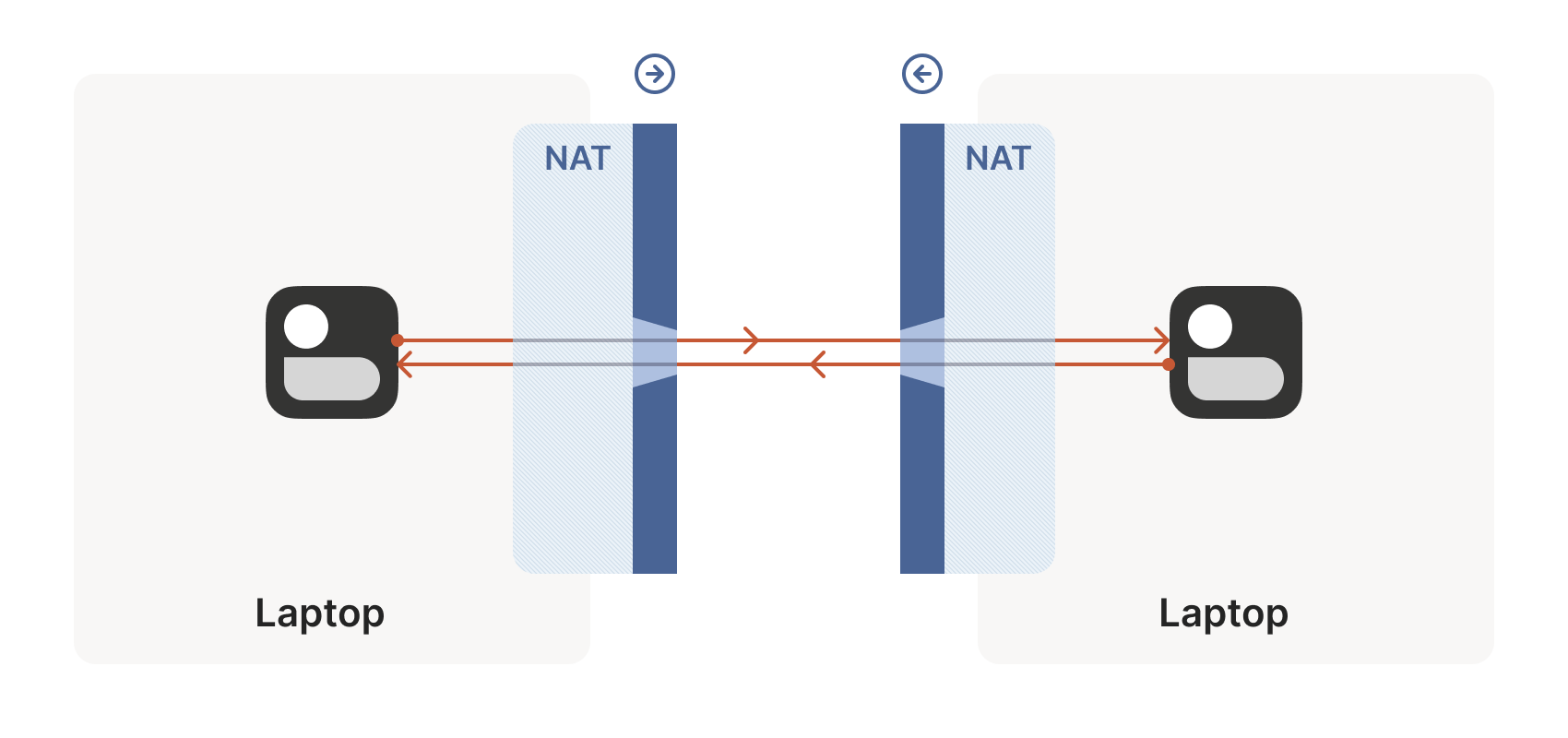
1.2 Requirement: Point-to-Point Connection Between Two NATed Machines
Given the NAT context described above, we start with the simplest problem: how to establish a point-to-point connection (direct connection) between two machines behind NATs, as shown below:
Directly connecting using the machines’ IP addresses is clearly impossible, as they are private IPs (e.g., 192.168.1.x). In Tailscale, we establish a WireGuard® tunnel to address this issue—but this isn’t the main focus, as we’ve integrated decades of efforts into a toolkit that applies broadly to various scenarios. For example:
- WebRTC uses these techniques for peer-to-peer voice, video, and data transfer between browsers.
- VoIP phones and some video games employ similar mechanisms, though not always successfully.
Next, this article will discuss these techniques in a general sense, using Tailscale and other examples where appropriate.
1.3 Solution: NAT Traversal
1.3.1 Two Essential Prerequisites: UDP and Direct Socket Control
To design your own protocol for NAT traversal, two conditions must be met:
The protocol should be based on UDP.
In theory, TCP could work, but it adds another layer of complexity to an already challenging problem, potentially requiring custom kernel modifications depending on the desired implementation. This article will focus on UDP.
If you’re considering TCP for a stream-oriented connection during NAT traversal, consider using QUIC instead. Built on UDP, QUIC allows us to focus on UDP NAT traversal while still providing a robust stream protocol.
Direct control over the socket for sending and receiving packets.
From experience, it’s impractical to implement NAT traversal using an existing network library, as we must send and receive additional packets outside the “main” protocol.
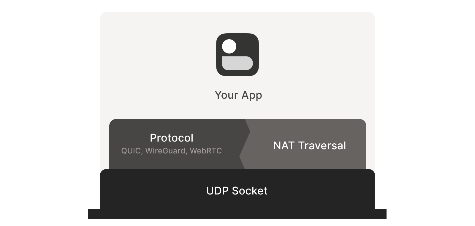
Some protocols (e.g., WebRTC) tightly integrate NAT traversal with other components. However, if building your own protocol, it’s recommended to treat NAT traversal as a separate entity running parallel to the main protocol, with both sharing the same socket, as shown below. This approach is highly beneficial:
1.3.2 Fallback Method: Relay
In some scenarios, direct socket access may be difficult to achieve.
A fallback approach is to set up a local proxy. The main protocol communicates with this proxy, which handles NAT traversal and relays packets to the peer. This introduces an extra layer of indirection but offers:
- The ability to still achieve NAT traversal.
- No modifications required to existing applications.
1.4 Challenges: Stateful Firewalls and NAT Devices
With the above foundation, let’s start from basic principles and explore how to implement an enterprise-grade NAT traversal solution step by step.
Our goal is to enable bidirectional UDP communication between two devices. With this foundation, higher-layer protocols (WireGuard, QUIC, WebRTC, etc.) can build more advanced functionality.
However, even this seemingly basic function requires overcoming two obstacles:
- Stateful firewalls
- NAT devices
Stateful firewalls are the relatively easier of the two to address. In fact, most NAT devices include a stateful firewall, so solving the second problem requires first tackling the first.
Stateful firewalls come in various forms, some of which you may have encountered:
- Windows Defender Firewall
- Ubuntu’s ufw (using iptables/nftables)
- BSD/macOS
pf - AWS Security Groups
2.1 Stateful Firewalls
2.1.1 Default Behavior (Policy)
The configurations of the above firewalls are highly flexible, but most default to the following behavior:
- Allow all outbound connections.
- Block all inbound connections.
There may be minor exceptions, such as allowing inbound SSH.
2.1.2 Distinguishing Inbound and Outbound Packets
Connections and directions are concepts in the protocol designer’s mind. At the physical transport layer, every connection is bidirectional, allowing packets to flow both ways. So, how does a firewall distinguish between inbound and outbound packets? This brings us to the term “stateful”: a stateful firewall keeps track of every packet it sees and uses this state to decide what to do with the next packet.
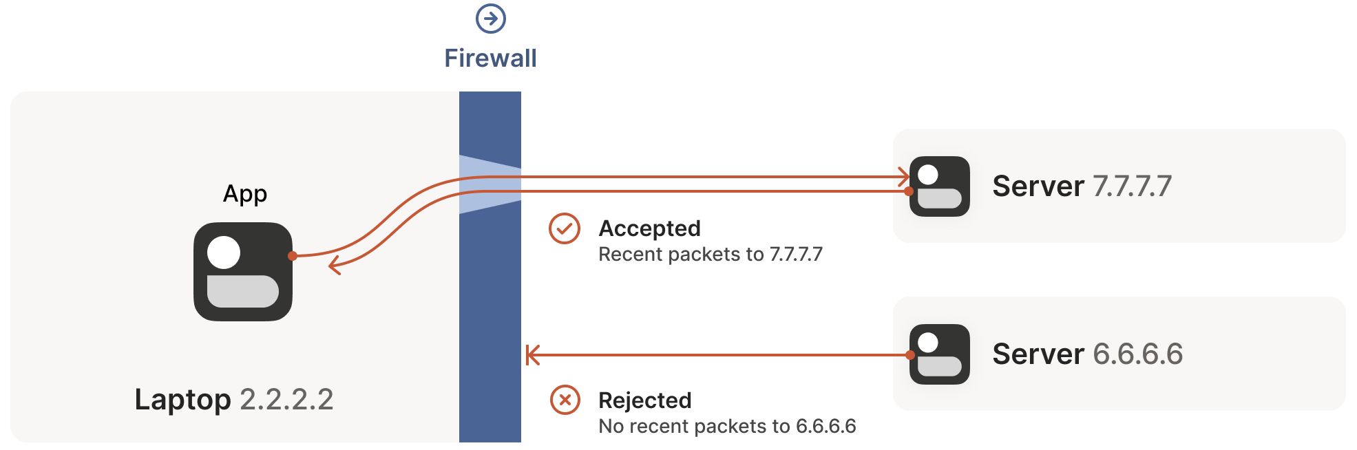
For UDP, the rule is simple: if the firewall has previously seen an outbound packet, it allows the corresponding inbound packet to pass. Consider the example below:
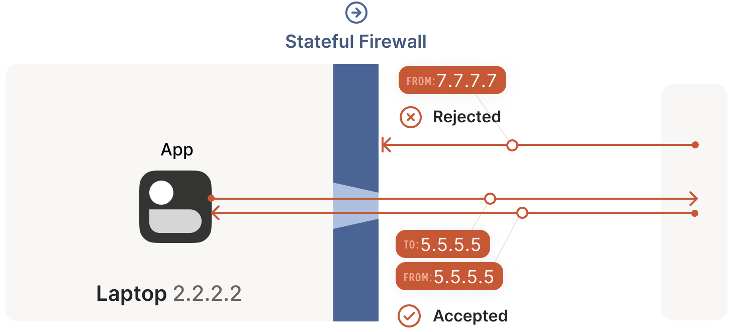
A laptop has a built-in firewall. When the firewall sees an outbound packet from the laptop, 2.2.2.2:1234 -> 5.5.5.5:5678, it records that inbound packets from 5.5.5.5:5678 -> 2.2.2.2:1234 should be allowed. The logic is: the trusted world (the laptop) wants to actively communicate with 5.5.5.5:5678, so the return path should be permitted.
Some very permissive firewalls allow all inbound traffic to
2.2.2.2:1234as long as they’ve seen any outbound packet from2.2.2.2:1234. These firewalls are extremely NAT-traversal-friendly but are increasingly rare.
2.2 Firewall Orientation (Face-Off) and Traversal Solutions
2.2.1 Same Firewall Orientation
Scenario Characteristics: Server IP Directly Accessible
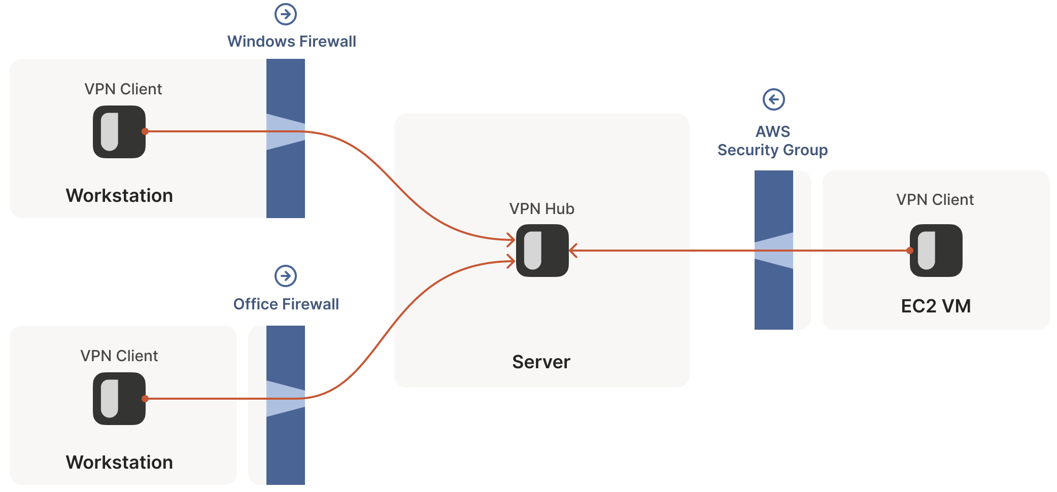
In NAT traversal scenarios, the default firewall rules have minimal impact on UDP traffic—as long as all firewalls in the path have the same “orientation”. This is typically the case when accessing a server on the public internet from a private network.
The only requirement is that the connection must be initiated by the machine behind the firewall. This is because no one can actively connect to it until it initiates communication with someone else, as shown below:
Traversal Solution: Client Connects Directly to Server or Hub-and-Spoke Topology
However, the above assumes that one of the communicating parties (the server) is directly accessible. In VPN scenarios, this forms the so-called hub-and-spoke topology: the central hub has no firewall restrictions, making it accessible to all; the spokes, behind firewalls, connect to the hub, as shown below:
2.2.2 Different Firewall Orientation
Scenario Characteristics: Server IP Not Directly Accessible
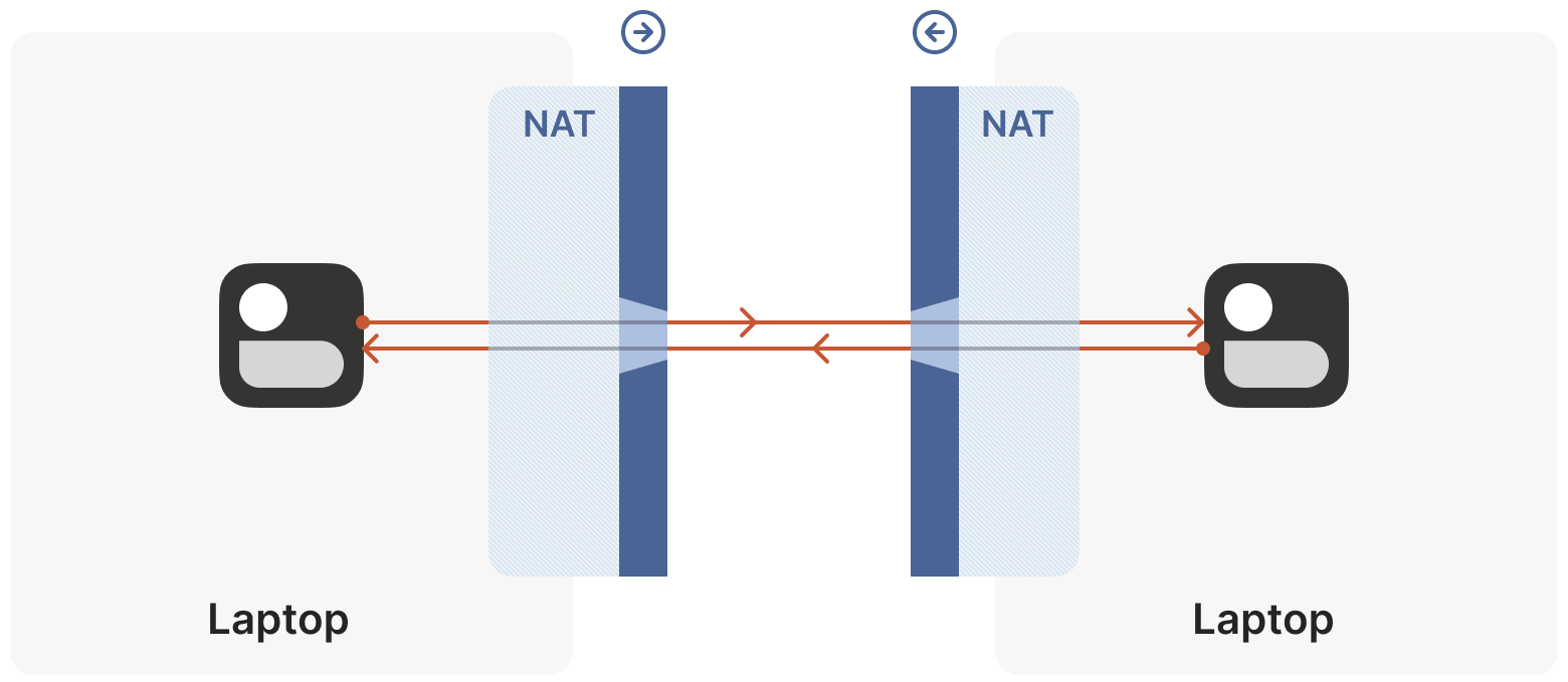
If two “clients” want to connect directly, the above approach fails, as the firewalls on both sides face each other, as shown below:
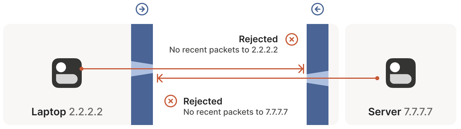
Based on the earlier discussion, this means both sides must initiate connection requests simultaneously, but it also implies that neither can initiate an effective request until the other side initiates first to open a hole in its firewall! How do we break this deadlock? One option is to have the user reconfigure one or both firewalls to open a port for the other’s traffic.
- This is clearly user-unfriendly and lacks scalability in mesh networks like Tailscale, where we assume peers move across the public internet with some granularity.
- Moreover, users often lack control over the firewall: for example, at a café or airport, the router you connect to is beyond your control (otherwise, you might be in trouble).
Thus, we need a method that doesn’t require firewall reconfiguration.
Traversal Solution: Both Sides Actively Initiate Connections, Opening a Hole in Local Firewalls
The solution begins by revisiting the stateful firewall rules mentioned earlier:
- For UDP, the rule (logic) is: packets must go out before packets can come in.
- Note that, beyond matching the packet’s IP and port, there’s no requirement that the packets be related. In other words, as long as some packets with the correct source and destination addresses are sent out, any packet that appears to be a response will be allowed by the firewall—even if the peer never received the outgoing packet.
Thus, to traverse these stateful firewalls, we only need to share some information: let both sides know the other’s ip:port in advance:
- Manual static configuration is one approach, but it’s obviously not scalable.
- We developed a coordination server to synchronize
ip:portinformation in a flexible, secure manner.
With the peer’s ip:port, both sides begin sending UDP packets to each other. During this process, we expect some packets to be dropped. Thus, both sides must accept that some packets will be lost, and if the information is critical, you must handle retransmissions yourself. Packet loss is acceptable for UDP, but it’s especially important to account for here.
Let’s examine the specific connection (traversal) process:
As shown below, the laptop sends its first packet,
2.2.2.2:1234 -> 7.7.7.7:5678, which passes through the Windows Defender firewall to the public internet.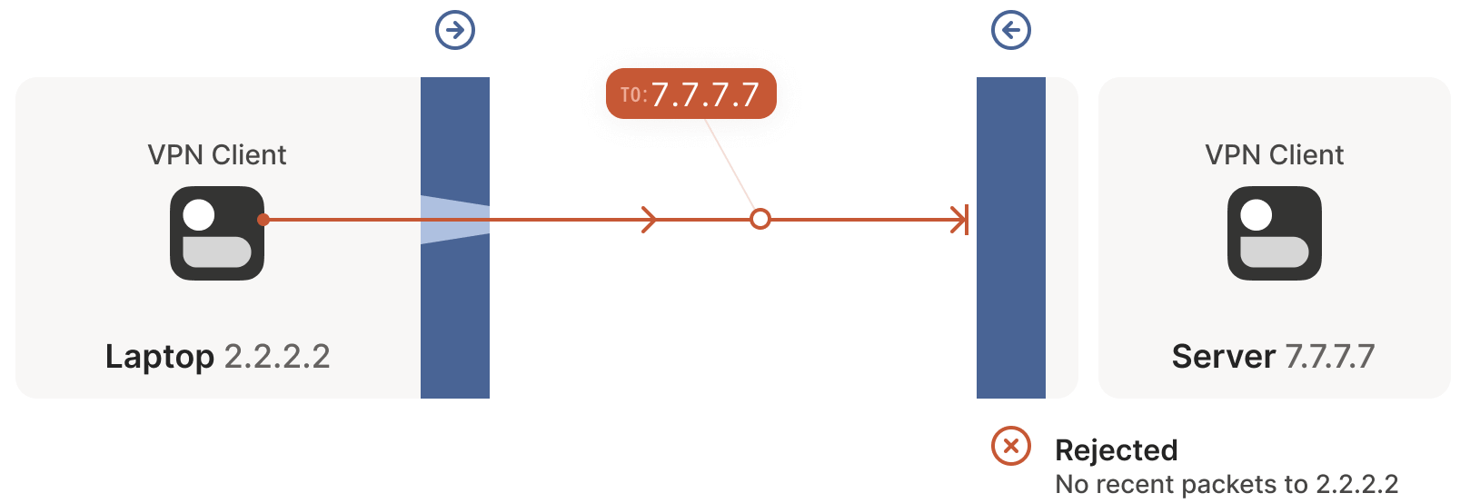
The peer’s firewall drops this packet because it has no record of traffic from
7.7.7.7:5678 -> 2.2.2.2:1234. However, Windows Defender now records the outbound connection, allowing response packets from7.7.7.7:5678 -> 2.2.2.2:1234to pass.Next, the first packet from
7.7.7.7:5678 -> 2.2.2.2:1234passes through its own firewall to the public internet.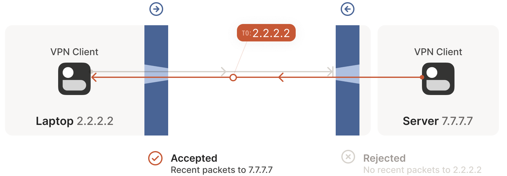
Upon reaching the client side, Windows Defender considers this a response to the earlier outbound packet and allows it through! Additionally, the right-side firewall now records that packets from
2.2.2.2:1234 -> 7.7.7.7:5678should be allowed.After receiving the server’s packet, the laptop sends a response packet. This packet passes through both the Windows Defender firewall and the server’s firewall (as it’s a response to the server’s packet) and reaches the server.
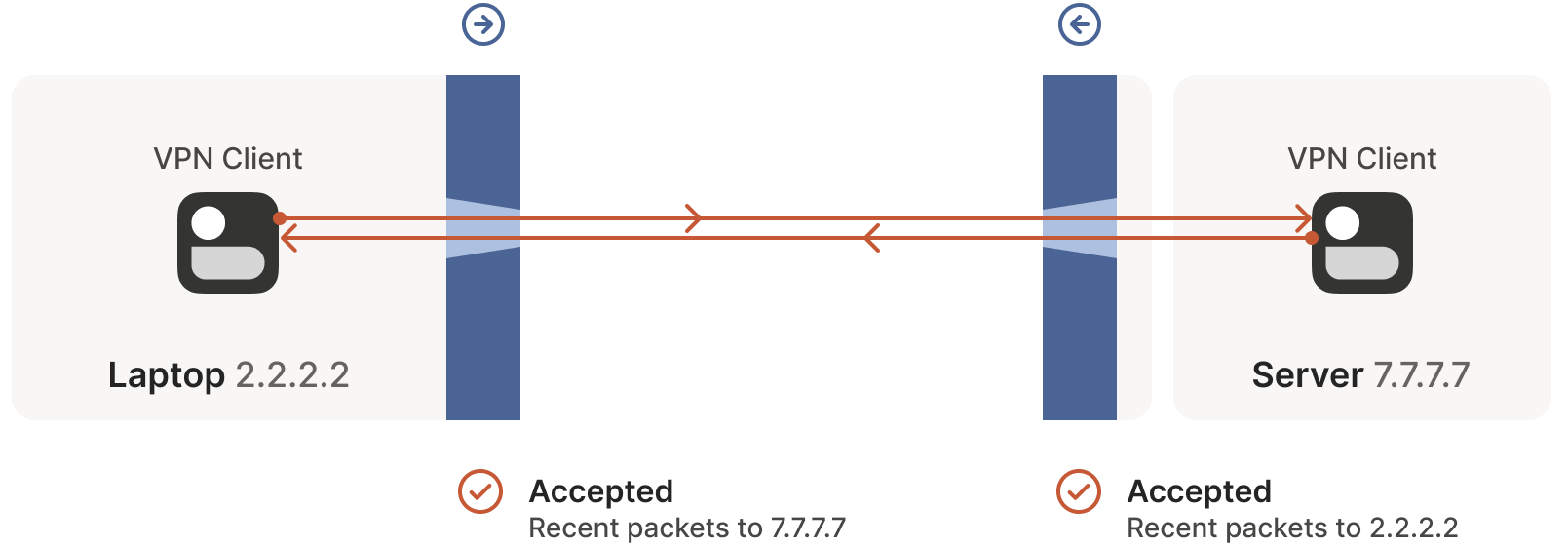
Success! We’ve established a bidirectional communication connection that traverses two opposing firewalls. At first glance, this task seemed impossible.
2.3 Reflections on Firewall Traversal
Traversing firewalls isn’t always this straightforward; sometimes, indirect effects from third-party systems require careful handling. What should we consider when traversing firewalls? A key point is that both communicating parties must initiate communication almost simultaneously to open a hole in the firewalls along the path while both endpoints remain active.
2.3.1 Simultaneous Connection Initiation: Side Channel
How do we achieve “simultaneity”? One approach is for both sides to keep retrying, but this is clearly resource-intensive. It would be ideal if both sides knew when to start initiating the connection.
This sounds like a chicken-and-egg problem: to communicate, both sides must first exchange a signal.
In practice, we can achieve this using a side channel, which doesn’t need to be sophisticated: it can tolerate a few seconds of latency and only needs to transmit a few KB of data. Even a low-spec virtual machine can provide side-channel communication for thousands of devices.
- In the distant past, I used XMPP chat messages as a side channel, and it worked remarkably well.
- Another example is WebRTC, which requires you to provide your own “signaling channel” (a term that hints at WebRTC’s IP telephony roots) and configure it in the WebRTC API.
- At Tailscale, our coordination server and DERP (Detour Encrypted Routing Protocol) server cluster serve as our side channel.
2.3.2 Inactive Connections Cleared by Firewalls
Stateful firewalls typically have limited memory, so they periodically clear inactive connections (commonly after 30 seconds for UDP). To keep a connection alive, regular communication is necessary to prevent the firewall from closing it. To avoid this issue, we can:
- Periodically send packets to the peer to keep the connection alive.
- Use an out-of-band method to rebuild the connection on demand.
2.3.3 All Problems Solved? No, the Challenges Are Just Beginning
For firewall traversal, we don’t need to worry about how many firewalls are in the path—as long as they are stateful and allow outbound connections, this simultaneous transmission mechanism can traverse any number of firewalls. This is very friendly to us, as we only need to implement one logic that works everywhere.
… Right?
Actually, not entirely. This mechanism assumes we can know the peer’s ip:port in advance. This brings us to the main topic of this article: NAT, which quickly erases the sense of accomplishment we just gained.
Below, we dive into the core of the article.
3.1 NAT Devices and Stateful Firewalls
A NAT device can be considered an enhanced stateful firewall, though its enhancements are not particularly welcome in our context: beyond the stateful blocking/passing functions mentioned earlier, NAT devices also modify packets as they pass through.
3.2 NAT Traversal and SNAT/DNAT
Specifically, NAT devices perform certain types of network address translation, such as replacing source or destination IP addresses or ports.
- When discussing connectivity and NAT traversal, we are only affected by source NAT (SNAT).
- DNAT does not impact NAT traversal.
3.3 Significance of SNAT: Addressing IPv4 Address Shortage
The most common use case for SNAT is connecting many devices to the public internet using only a few public IPs. For example, a consumer-grade router maps all devices’ (private) IP addresses to a single public IP address.
The purpose of this approach is that we have far more devices needing public internet access than available public IPs (at least for IPv4; IPv6 is discussed later). NAT allows multiple devices to share a single IP address, enabling the internet to scale despite the IPv4 address shortage.
3.4 SNAT Process: Example of a Home Router
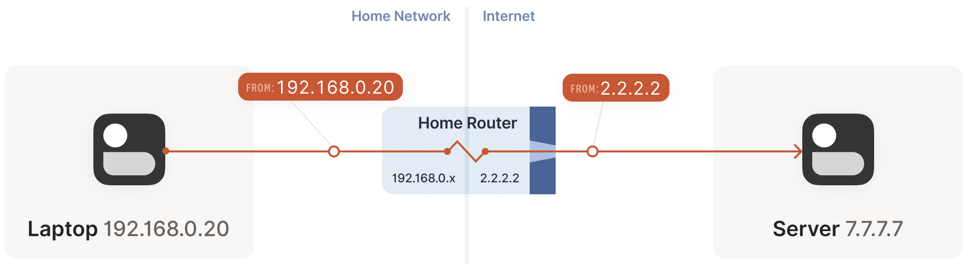
Suppose your laptop is connected to your home Wi-Fi. Let’s examine what happens when it connects to a public internet server:
The laptop sends a UDP packet
192.168.0.20:1234 -> 7.7.7.7:5678.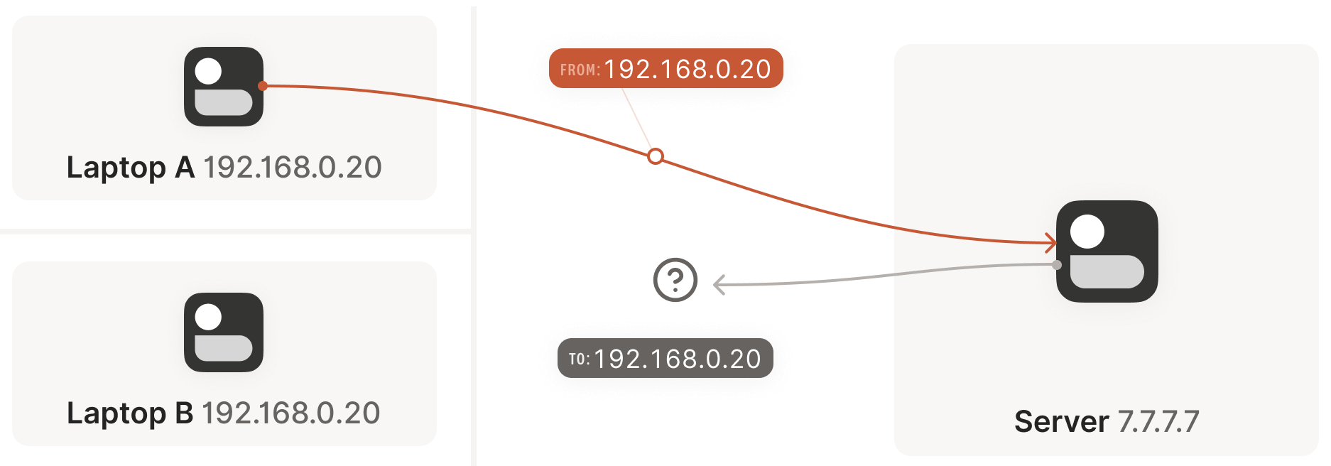
This step is as if the laptop had a public IP, but the source address
192.168.0.20is private, valid only within the private network. The public internet doesn’t recognize it and wouldn’t know how to respond to such a packet.The home router steps in and performs SNAT.
As the packet passes through the router, the router detects it as a new session it hasn’t seen before. It knows
192.168.0.20is a private IP, and the public internet can’t send responses to it, but it has a solution:- It selects an available UDP port on its own public IP, e.g.,
2.2.2.2:4242. - It creates a NAT mapping:
192.168.0.20:1234<-->2.2.2.2:4242. - It sends the packet to the public internet, with the source address now
2.2.2.2:4242instead of192.168.0.20:1234. Thus, the server sees the translated address. - Subsequently, every packet matching this mapping rule has its IP and port rewritten by the router.
- It selects an available UDP port on its own public IP, e.g.,
The reverse path is similar: the router performs the inverse address translation, converting
2.2.2.2:4242back to192.168.0.20:1234. The laptop is unaware of these bidirectional transformations.
This example uses a home router, but the principle is the same for office networks. The difference is that office network NATs may consist of multiple devices (for high availability, capacity, etc.) and have more than one public IP available, providing a larger pool for selecting public ip:port mappings to support more clients.
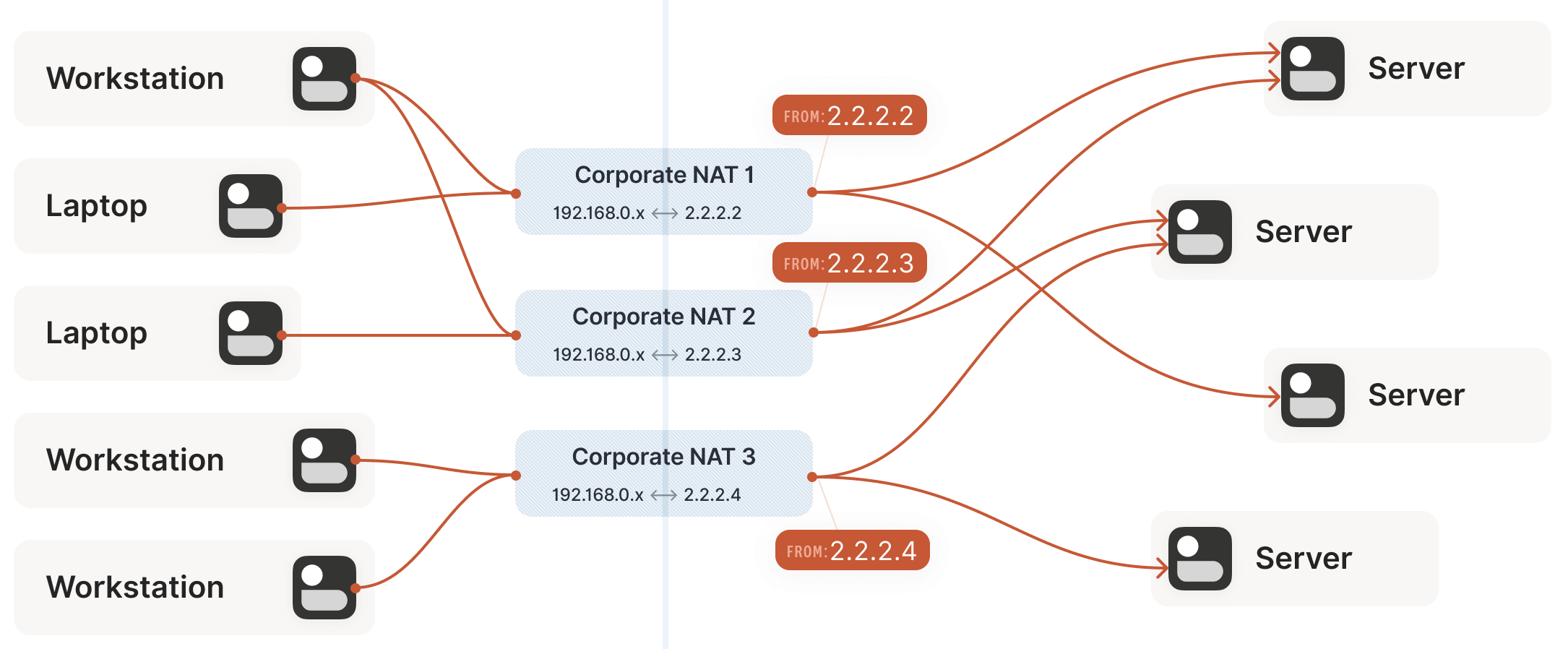
3.5 Challenges SNAT Poses to Traversal
Now we face a situation similar to the stateful firewall scenario, but this time with NAT devices: neither communicating party knows the other’s ip:port, making it impossible to initiate a connection, as shown below:
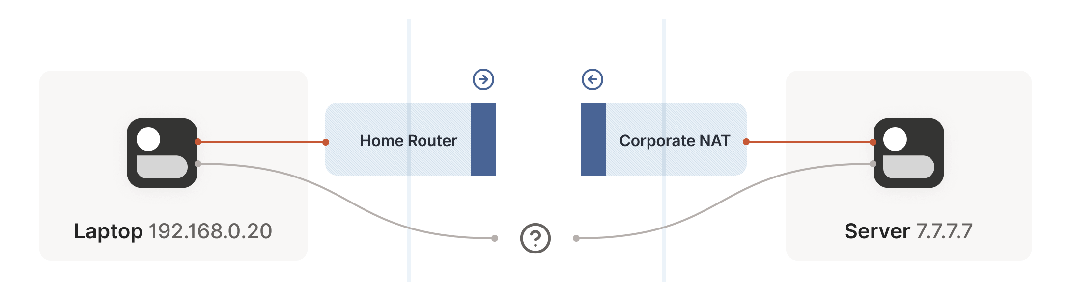
This is worse than the firewall case. Strictly speaking, neither side can determine their own or the other’s ip:port until packets are sent, because a NAT mapping (the ip:port the other side can connect to) is only created after an outbound packet passes through the router.
Thus, we’re back to the firewall problem, but in a worse form: both sides need to initiate a connection with the other but don’t know the other’s public address. We can only obtain the peer’s address after they send a packet first.
How do we break this deadlock? Enter STUN.
STUN is both a detailed study of NAT device behavior and a protocol to assist with NAT traversal. This article focuses on the STUN protocol.
4.1 STUN Principles
STUN is based on a simple observation: when a NATed client accesses a public internet server, the server sees the NAT device’s public ip:port, not the client’s local network ip:port.
In other words, the server can tell the client what ip:port it sees for the client. By sharing this information with the communication peer in some way, the peer knows which address to connect to! This reduces the problem to the firewall traversal issue discussed earlier.
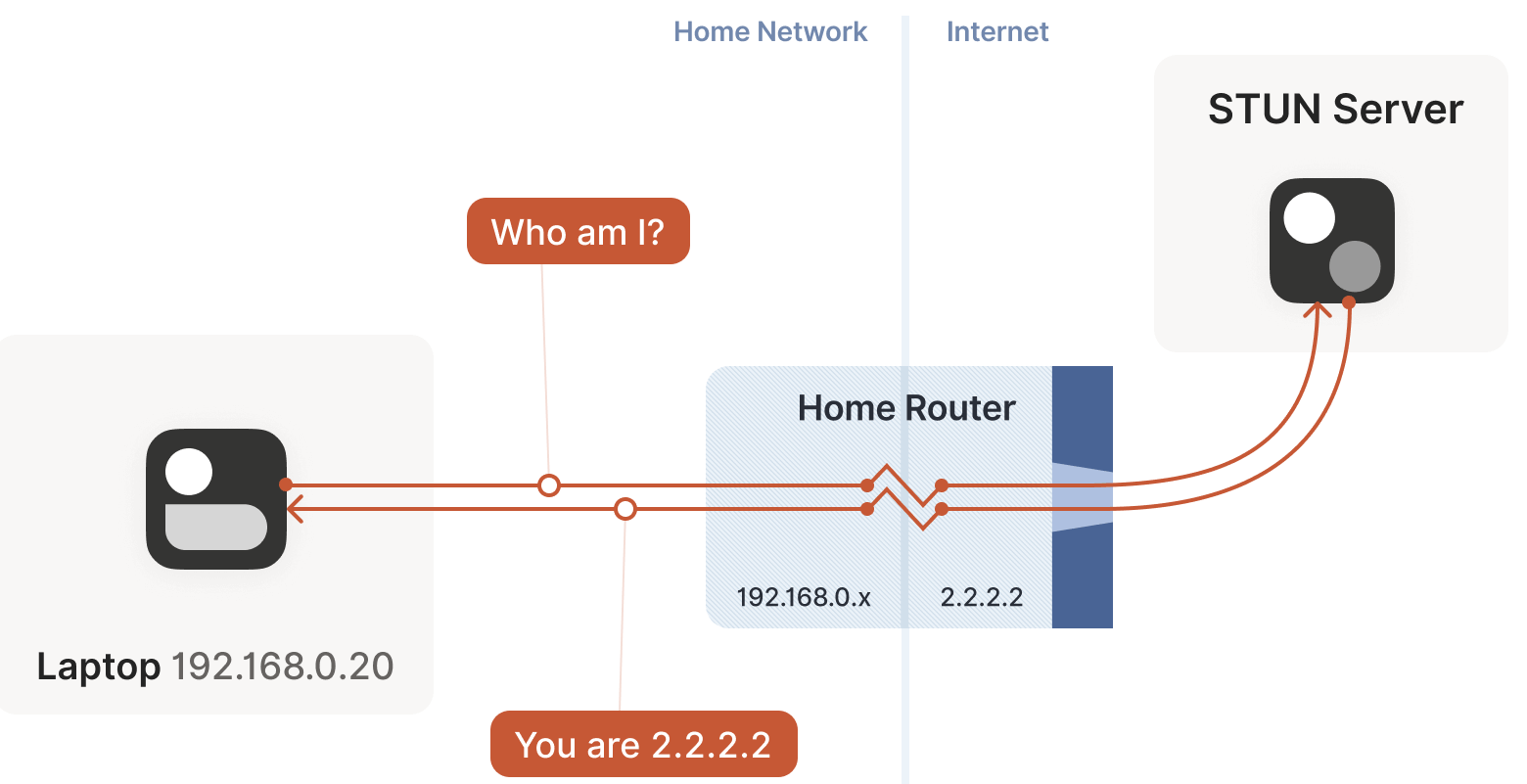
This is essentially how the STUN protocol works, as shown below:
- The laptop sends a request to the STUN server: “From your perspective, what’s my address?”
- The STUN server responds: “I see your UDP packet coming from this address:
ip:port.”
The STUN protocol has a bunch more stuff in it — there’s a way of obfuscating the
ip:portin the response to stop really broken NATs from mangling the packet’s payload, and a whole authentication mechanism that only really gets used by TURN and ICE, sibling protocols to STUN that we’ll talk about in a bit. We can ignore all of that stuff for address discovery.
4.2 Why NAT Traversal Logic and Main Protocol Must Share the Same Socket
Understanding STUN’s principles clarifies why we stated at the beginning that to implement your own NAT traversal logic alongside the main protocol, both must share the same socket:
- Each socket corresponds to a single mapping on the NAT device (private address -> public address).
- The STUN server is merely an auxiliary infrastructure for traversal.
- After communicating with the STUN server, a connection is opened on the NAT and firewall devices, allowing inbound packets (recall that as long as the destination address is correct, UDP packets can come in, regardless of whether they’re from the STUN server).
- Thus, by sharing this address with the communication peer and having them send packets to it, traversal is achieved.
4.3 STUN’s Limitation: Inability to Traverse All NAT Devices (e.g., Enterprise NAT Gateways)
With STUN, it seems we’ve achieved our traversal goal: each machine uses STUN to obtain the public ip:port corresponding to its private socket, shares this with the peer, and both sides simultaneously attempt firewall traversal, following the same process as the firewall traversal section. Right?
The answer is: it depends. In some cases, yes, but in others, no. Generally:
- For most home router scenarios, this approach works fine.
- For some enterprise NAT gateways, it fails.
The more a NAT device’s documentation emphasizes its security, the more likely STUN will fail. (Note, however, that NAT devices do not inherently enhance network security in any meaningful way, but this is beyond the scope of this article.)
4.4 Revisiting STUN’s Assumptions
Let’s reexamine the assumption about STUN: when the STUN server tells the client its public address is 2.2.2.2:4242, all packets destined for 2.2.2.2:4242 should traverse the firewall to reach the client.
This is precisely the issue: this assumption doesn’t always hold.
Some NAT devices behave as we assumed: their stateful firewall component allows corresponding inbound packets as long as it sees an outbound packet initiated by the client. Thus, using STUN and simultaneous firewall traversal can establish the connection.
In theory, there are also NAT devices that are super relaxed and don’t ship with stateful firewall stuff at all. In those, you don’t even need simultaneous transmission; the STUN request gives you an internet
ip:portthat anyone can connect to with no further ceremony. If such devices do still exist, they’re increasingly rare.Other NAT devices are far more challenging: they generate a distinct mapping for each destination address. On such devices, if we use the same socket to send packets to
5.5.5.5:1234and7.7.7.7:2345, we get two different ports on2.2.2.2, one for each destination. If the return packet uses the wrong port, it won’t pass the firewall, as shown below: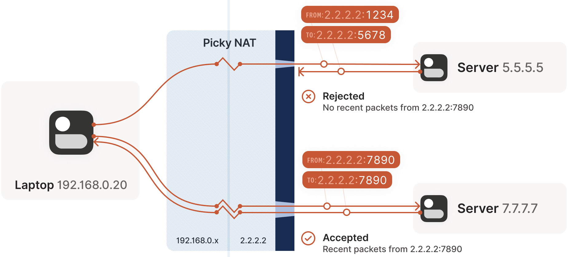
Now that we know NAT device behavior varies, let’s introduce some formal terminology.
5.1 Early Terminology
If you’ve previously encountered NAT traversal, you may have heard terms like:
- “Full Cone”
- “Restricted Cone”
- “Port-Restricted Cone”
- “Symmetric” NATs
These are early terms in the NAT traversal field.
However, these terms are quite confusing. I have to look up what Restricted Cone NAT means every time. From practical experience, I’m not the only one confused. For instance, today, the internet often classifies “easy” NATs as Full Cone, when they’re more accurately Port-Restricted Cone.
5.2 Recent Research and New Terminology
Recent studies and RFCs have introduced more precise terminology.
- First, they clarify that NAT device behavior varies across multiple dimensions, not just the single “cone” dimension described in early research. Thus, classifying based on “cone” isn’t very helpful.
- Second, new research and terminology more accurately describe what NATs do.
The so-called “easy” and “hard” NATs differ in one dimension: whether the NAT mapping considers destination address information. In RFC 4787:
Easy NAT and its variants are called “Endpoint-Independent Mapping” (EIM).
However, in the grand programmer tradition of “naming is hard”, the term EIM isn’t 100% accurate, as this NAT still depends on the endpoint—just the source endpoint: each source
ip:portcorresponds to one mapping. Otherwise, your packets would mix with others’, causing chaos.Strictly speaking, EIM should be called “Destination Endpoint Independent Mapping” (DEIM?), but this is too cumbersome, and by convention, Endpoint always refers to the Destination Endpoint.
Hard NAT and its variants are called “Endpoint-Dependent Mapping” (EDM).
EDM has a subtype based on whether the mapping depends on
dst_ipalone or bothdst_ipanddst_port. For NAT traversal, this distinction is irrelevant: both make STUN unusable.
5.3 Legacy Cone Type Classification
You might wonder: if dependency on the endpoint yields only two possibilities, why did the traditional classification include four cone types? The answer is that cone encompasses two orthogonal dimensions of NAT behavior:
- NAT mapping behavior: As discussed earlier.
- Stateful firewall behavior: Similarly, divided into endpoint-dependent or endpoint-independent types.
Thus, the final combinations are as follows:
NAT Cone Types
| Endpoint-Independent NAT Mapping | Endpoint-Dependent NAT Mapping (all types) | |
|---|---|---|
| Endpoint-Independent Firewall | Full Cone NAT | N/A* |
| Endpoint-Dependent Firewall (dst. IP only) | Restricted Cone NAT | N/A* |
| Endpoint-Dependent Firewall (dst. IP+port) | Port-Restricted Cone NAT | Symmetric NAT |
Breaking it down to this level reveals that cone types are largely irrelevant for NAT traversal scenarios. We care about one thing: whether it’s Symmetric—in other words, whether a NAT device is EIM or EDM.
5.4 Simplified NAT Classification for Traversal Scenarios
The above discussion shows that while understanding firewall behavior is important, it’s less critical for writing NAT traversal code. Our simultaneous packet transmission approach can effectively traverse all three firewall types above. In real-world scenarios, we primarily deal with IP-and-port endpoint-dependent firewalls.
Thus, for practical NAT traversal implementation, we can simplify the classification to:
| Endpoint-Independent NAT Mapping | Endpoint-Dependent NAT Mapping (dst. IP only) | |
|---|---|---|
| Firewall is yes | Easy NAT | Hard NAT |
5.5 Additional NAT Specifications (RFCs)
To learn more about new NAT terminology, refer to:
If implementing your own NAT, you should follow these RFC specifications to ensure your NAT behavior aligns with industry standards and is compatible with other vendors’ devices or software.
6.1 Problem Recap and Fallback Method (Relay)
Having covered the foundational knowledge (especially defining what a hard NAT is), let’s return to our NAT traversal theme.
- Sections 1–4 have addressed STUN and firewall traversal.
- However, hard NATs pose a significant problem: if even one such device is in the path, the previous solutions fail.
Ready to give up? This is where NAT traversal gets truly challenging: what do we do if all the methods introduced so far still fail to traverse?
- In fact, many NAT implementations give up in such cases, reporting an error like “Unable to connect” to the user.
- For us, giving up so quickly is unacceptable—failing to solve connectivity issues would render Tailscale pointless.
Our fallback solution is to create a relay connection to enable seamless communication between the parties. But isn’t relay performance poor? It depends:
- If a direct connection is possible, there’s no need for a relay.
- If a direct connection isn’t possible, but the relay path closely approximates the real direct path and has sufficient bandwidth, the relay won’t significantly degrade communication quality. Latency will increase slightly, and bandwidth will be consumed, but it’s far more acceptable than no connection at all.
Note that we only resort to relays when direct connections fail. In practice:
- For most networks, we can achieve direct connections using the methods introduced earlier.
- For the remaining cases, Tailscale uses relays, which isn’t a bad solution.
Additionally, some networks block NAT traversal entirely, posing a greater challenge than hard NATs. For example, we’ve observed that UC Berkeley’s guest Wi-Fi blocks all outbound UDP traffic except DNS. No NAT traversal technique can bypass this restriction. Thus, we ultimately need a reliable fallback mechanism.
6.2 Relay Protocols: TURN, DERP
There are several relay implementations:
TURN (Traversal Using Relays around NAT): The classic approach, with the core idea being:
- The user authenticates with a public TURN server, which responds: “I’ve allocated an
ip:portfor you and will relay your traffic.” - Share this
ip:portwith the peer, who connects to it, followed by a straightforward client/server communication model.
Tailscale does not use TURN. This protocol is not user-friendly, and unlike STUN, it lacks true interactivity, as there are no public TURN servers on the internet.
- The user authenticates with a public TURN server, which responds: “I’ve allocated an
DERP (Detoured Encrypted Routing Protocol)
This is a protocol we created, DERP:
- It’s a general-purpose packet relay protocol running over HTTP, which most networks allow.
- It relays encrypted payloads based on the destination’s public key.
As briefly mentioned earlier, DERP serves as both our fallback communication method when NAT traversal fails (similar to TURN) and a side channel in other scenarios to assist with NAT traversal. In other words, it’s both our fallback and infrastructure to upgrade to a peer-to-peer connection when a better traversal path is available.
6.3 Summary
With the “relay” fallback, our traversal success rate increases significantly. If you stop reading here and implement the traversal methods described so far, I estimate:
- In 90% of cases, you’ll achieve direct traversal.
- In the remaining 10%, relays will handle some cases.
This is already a “good enough” traversal implementation.
If “good enough” isn’t sufficient, there’s much more we can do!
This section introduces a variety of tricks that help in specific scenarios. Individually, these techniques can’t solve NAT traversal, but cleverly combining them brings us closer to a 100% traversal success rate.
7.1 Traversing Hard NAT: Brute-Force Port Scanning
Recall the issue with hard NATs, as shown below. The key problem is that the easy NAT side doesn’t know which ip:port to send packets to on the hard NAT side.
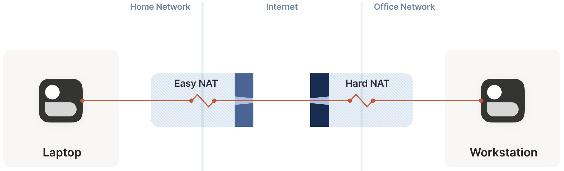
We must send packets to the correct ip:port to traverse the firewall and achieve bidirectional communication. What can we do?
First, we can obtain some
ip:portinformation for the hard NAT side via the STUN server.Here, we assume the IP addresses obtained are correct (not always true, but we’ll assume so for now. In practice, this is usually the case; see REQ-2 in RFC 4787 for details).
With the IP address determined, the remaining issue is the port. There are 65,535 possibilities. Can we traverse this port range?
At a packet-sending rate of 100 packets/s, the worst-case scenario requires 10 minutes to find the correct port. As mentioned, this isn’t optimal, but it’s better than no connection.
This resembles port scanning (and it is), which may trigger the peer’s network intrusion detection software in practice.
7.2 Improving Brute-Force Scanning with Birthday Paradox: Hard Side Opens Multiple Ports + Easy Side Random Probes
Using the birthday paradox algorithm, we can improve port scanning.
- The previous section’s premise was that the hard side opens one port, and the easy side brute-forces all 65,535 ports to find it.
- The improvement here is to have the hard side open multiple ports, e.g., 256 (i.e., simultaneously open 256 sockets, all targeting the easy side’s
ip:port), while the easy side randomly probes these ports.
We’ll skip the mathematical model of the algorithm. If you’re interested in the implementation, check out my Python calculator. The calculation is a slight variation of the “classic” birthday paradox. Below is the probability of the two sides’ open ports overlapping (i.e., successful communication) as the number of random probes by the easy side increases (assuming the hard side opens 256 ports):
| Random Probes | Success Probability |
|---|---|
| 174 | 50% |
| 256 | 64% |
| 1024 | 98% |
| 2048 | 99.9% |
Based on these results, assuming a moderate probe rate of 100 ports/s, there’s about a 50% success probability in 2 seconds. Even in the worst case, we can achieve nearly 100% traversal success in 20 seconds, having probed only 4% of the total port space.
Excellent! While hard NATs introduce significant traversal latency, the end result is still successful. Can we handle a scenario with two hard NATs?
7.3 Dual Hard NAT Scenario
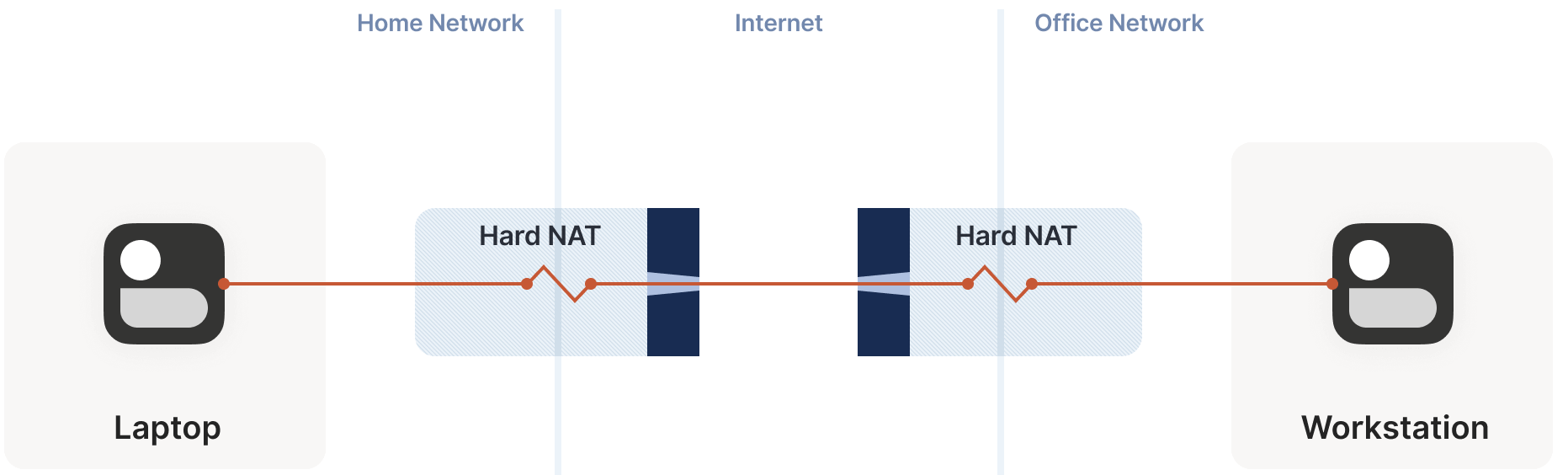
In this case, we can still use the multi-port + random probe approach, but the success probability is much lower:
- Each time we probe the peer’s ports (destination ports) through a hard NAT, we simultaneously generate a random source port.
- This means our search space becomes two-dimensional
{src port, dst port}pairs, rather than the previous one-dimensional destination port space.
We won’t delve into the calculations here, but the result is: assuming the destination opens 256 ports and the source initiates 2048 probes (20 seconds), the success probability is 0.01%.
If you’re familiar with the birthday paradox, this result isn’t surprising. Theoretically:
- To achieve a 99.9% success rate, both sides need to perform 170,000 probes—at 100 packets/s, this takes 28 minutes.
- For a 50% success rate, “only” 54,000 packets are needed, or 9 minutes.
- Without the birthday paradox and using brute-force enumeration, it would take 1.2 years!
For some applications, 28 minutes may still be acceptable. Spending half an hour to brute-force NAT traversal allows the connection to persist—unless the NAT device restarts, requiring another half-hour to re-establish. However, for interactive applications, this is clearly unacceptable.
Worse still, examining common office network routers reveals shockingly low active session limits. For example, a Juniper SRX 300 supports a maximum of 64,000 active sessions. This means:
- To create one successful traversal connection, we’d overwhelm its entire session table (since probing 65,535 ports creates a new connection record per probe)! This assumes the router can gracefully handle overload.
- This is just the impact of one connection! If 20 machines simultaneously attempt traversal on this router? Absolute disaster!
At this point, we’ve traversed more challenging network topologies than before. This is a significant achievement, as home routers are typically easy NATs, while hard NATs are usually office network routers or cloud NAT gateways. This approach helps solve:
- Home-to-office
- Home-to-cloud
scenarios, and partially addresses:
- Office-to-cloud
- Cloud-to-cloud
scenarios.
7.4 Controlling Port Mapping: UPnP/NAT-PMP/PCP Protocols
If we could simplify the NAT device’s behavior to avoid such complexity, establishing connections (traversal) would be much easier. Is this possible? Yes, there’s a dedicated class of protocols called port mapping protocols. By using these to bypass the complexities encountered earlier, we get a simple “request-response” interaction.
Below are three specific port mapping protocols:
UPnP IGD (Universal Plug’n’Play Internet Gateway Device)
The oldest port control protocol, born in the late 1990s, it uses many 1990s technologies (XML, SOAP, multicast HTTP over UDP—yes, HTTP over UDP), making it difficult to implement accurately and securely. However, many routers historically included UPnP, and many still do.
Request and response:
- “Hello, please forward my
lan-ip:portto the public internet (WAN).” - “Okay, I’ve allocated a public mapping
wan-ip:portfor you.”
- “Hello, please forward my
NAT-PMP
A few years after UPnP IGD, Apple introduced a similar protocol called NAT-PMP (NAT Port Mapping Protocol).
Unlike UPnP, this protocol only handles port forwarding, making it very simple to implement on both client and server sides.
PCP
Later, a version 2 of NAT-PMP emerged with a new name, PCP (Port Control Protocol).
To improve traversal, you can:
Check if the local default gateway supports UPnP IGD, NAT-PMP, or PCP.
If any of these protocols responds, request a public port mapping.
Think of this as an enhanced STUN: not only can we discover our public
ip:port, but we can also instruct our NAT device to be friendlier to our communication peer—though this doesn’t involve modifying or adding firewall rules for the port.Subsequently, any packets arriving at our NAT device with the address of our requested port will be forwarded to us.
However, we cannot assume these protocols are always available:
The local NAT device may not support the protocol.
The device may support it but have it disabled by default, or no one knows it exists, so it’s never enabled.
Security policies may require disabling this feature.
This is common, as UPnP has had high-severity vulnerabilities in the past (later fixed, so newer devices can safely use UPnP if implemented correctly). Unfortunately, some device configurations bundle UPnP, NAT-PMP, and PCP under a single switch (often labeled “UPnP” functionality), enabling or disabling all at once. If someone is concerned about UPnP’s security, they lose access to the other two as well.
Ultimately, as long as these protocols are available, they effectively reduce one NAT layer, greatly simplifying the connection process. Let’s now explore some less common scenarios.
7.5 Negotiating Multiple NATs
So far, we’ve seen clients and servers each with a single NAT device. What happens with multiple NAT devices? Consider the topology below:
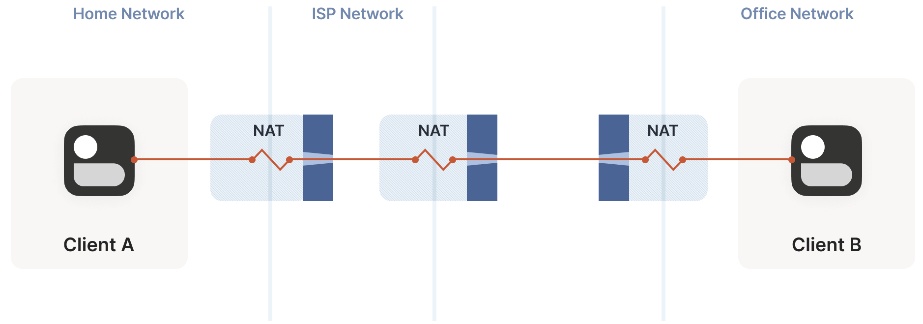
This example is relatively simple and doesn’t pose significant traversal challenges. The process of a packet from client A passing through multiple NATs to reach the public internet is analogous to traversing multiple stateful firewalls discussed earlier:
- The additional (NAT) layer is invisible to both client and server, and our traversal techniques don’t care how many layers are in between.
- The only layer that matters is the outermost one, as the peer needs to find an entry point at this layer to send packets in.
Specifically, the port forwarding protocol is what’s affected:
- When the client uses this protocol to allocate a port, the port is allocated by the NAT device closest to the client.
- We want the outermost NAT (farthest from the client) to allocate the port; otherwise, we get an
ip:portfrom an intermediate network layer, which the peer can’t use. - Unfortunately, none of these protocols can recursively inform us about the next NAT device—though tools like traceroute can probe the network path and guess which devices might be NATs (by attempting NAT requests). This relies on luck.
This explains why the internet is filled with articles about how terrible double-NAT is and warnings to avoid it for backward compatibility. In reality, double-NAT is transparent to most internet applications, as they don’t need to actively perform NAT traversal.
However, I’m not suggesting you set up double-NAT in your network:
- Disrupting port mapping protocols can break multiplayer modes in some video games.
- It may prevent your IPv6 network from being utilized, which is a great solution for direct bidirectional connectivity without NAT.
If double-NAT is beyond your control, most things remain unaffected except for the inability to use port mapping protocols.
Is the double-NAT story over? Not quite—larger-scale double-NAT scenarios await.
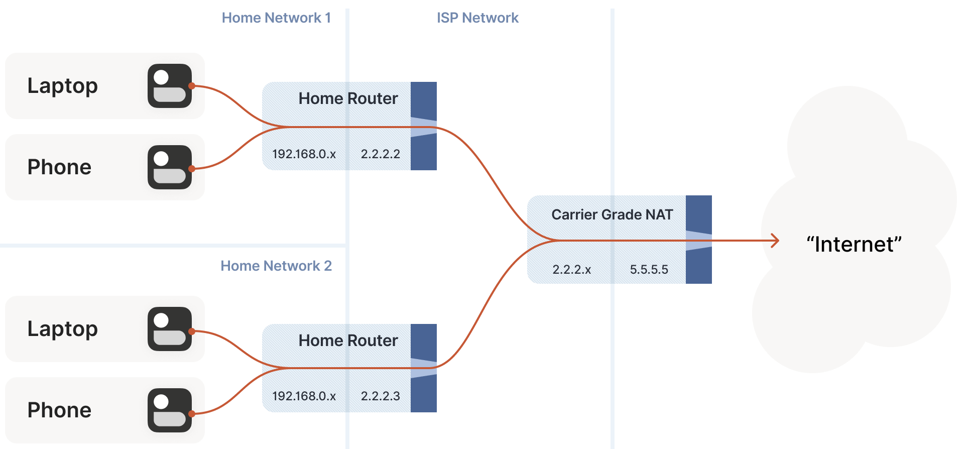
7.6 Issues Caused by Carrier-Grade NAT
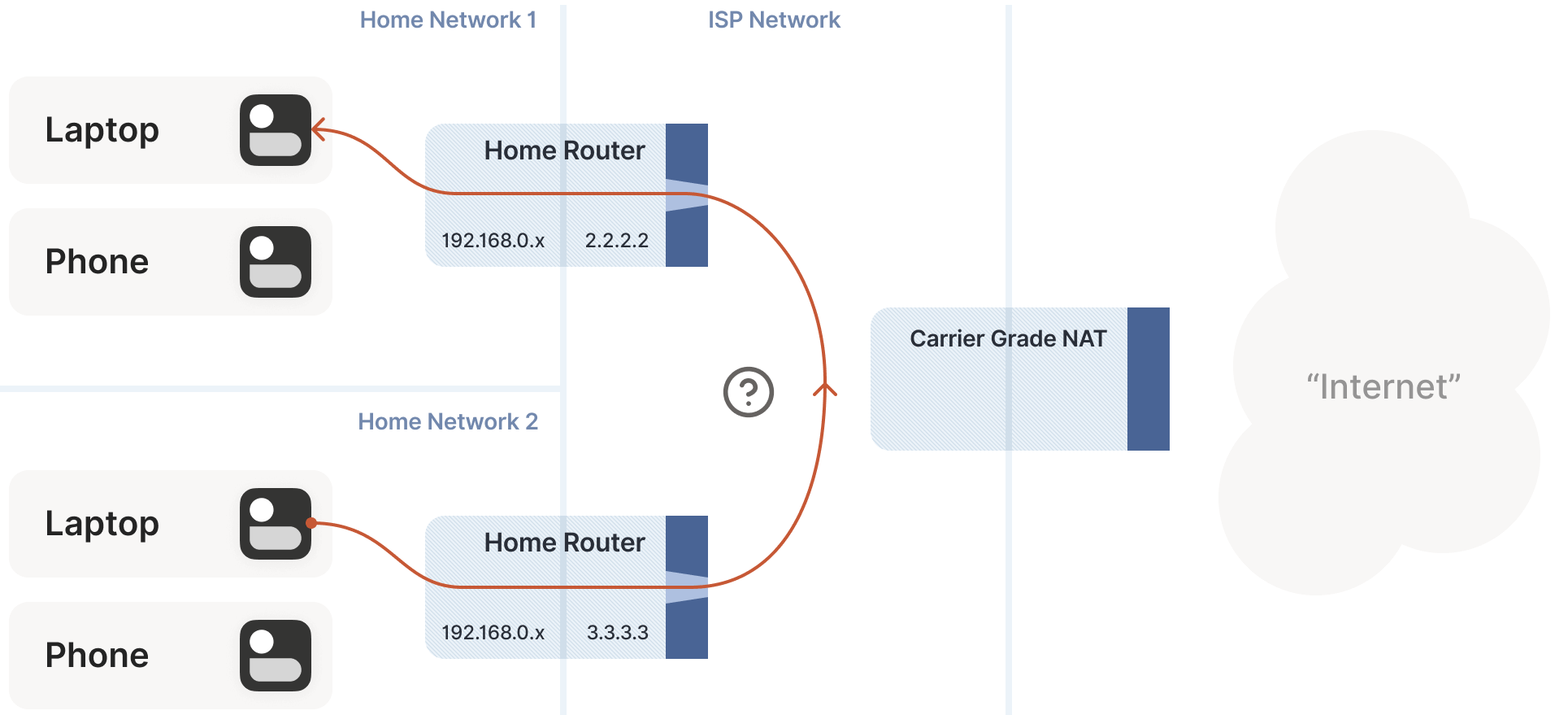
Even using NAT to address the IPv4 shortage, addresses remain insufficient. ISPs (Internet Service Providers) clearly cannot allocate a public IP to every household. How do they solve this? ISPs add another layer of NAT:
- The home router SNATs your client to an “intermediate” IP and sends it to the ISP’s network.
- The ISP’s network NAT device maps these intermediate IPs to a small pool of public IPs.
This latter NAT is called carrier-grade NAT (or telecom-grade NAT), abbreviated as CGNAT, as shown below:
CGNAT is a major headache for NAT traversal:
- Previously, office network users could achieve quick NAT traversal by manually setting port mappings on their routers.
- With CGNAT, this no longer works, as you can’t control the ISP’s CGNAT!
The good news is that this is a variant of double-NAT, so most of the solutions discussed earlier still apply. Some things may not work as expected, but paying the ISP can resolve these issues. Except for port mapping protocols, all the techniques we’ve covered remain applicable in CGNAT scenarios.
New Challenge: Direct Connection on the Same CGNAT Side, STUN Unusable
We do face a new challenge: how to directly connect two peers behind the same CGNAT but different home routers? As shown below:
In this case, STUN fails to work properly: STUN sees the client’s address as it appears on the public internet (behind the CGNAT), but we need the ip:port in the “middle network,” which is what the peer actually requires.
Solution: If Port Mapping Protocols Are Available, One Side Performs Port Mapping
What’s the solution?
If you thought of port mapping protocols, congratulations, you’re correct! If either peer’s NAT supports port mapping protocols, we can achieve traversal, as the allocated ip:port is exactly what the peer needs.
The irony here is that double-NAT (CGNAT) breaks port mapping protocols, but in this case, it saves us! Of course, we’re assuming these protocols are available, as CGNAT ISPs tend to disable them on their home routers to avoid software receiving “incorrect” results, which causes confusion.
Solution: If Port Mapping Protocols Are Unavailable, NAT Hairpin Mode
If we’re unlucky and the NAT lacks port mapping functionality, what then?
Let’s return to STUN-based techniques and see what happens. Both sides are on the same CGNAT side. Suppose STUN tells us A’s address is 2.2.2.2:1234 and B’s is 2.2.2.2:5678.
The next question is: what happens if A sends a packet to 2.2.2.2:5678? The expected CGNAT behavior is:
- Apply A’s NAT mapping rule, performing SNAT on
2.2.2.2:1234 -> 2.2.2.2:5678. - Notice that the destination
2.2.2.2:5678matches B’s inbound NAT mapping, so perform DNAT, changing the destination IP to B’s private address. - Send the packet to B via the CGNAT’s internal interface (not the public interface, corresponding to the public internet).
This NAT behavior has a specific term: hairpinning (literally “hairpin,” meaning it goes up one side and loops back down the other), as shown below:

As you might guess, not all NATs support hairpin mode. In fact, many well-behaved NAT devices don’t support it:
- They assume “only packets with a private src_ip and public dst_ip pass through me”.
- For packets where the destination isn’t public and needs to be routed back to the internal network, they drop them.
- This logic is often implemented directly in the router’s chipset, so changing it via software is impossible without hardware upgrades.
Hairpinning is a characteristic (supported or not) of all NAT devices, not unique to CGNAT:
In most cases, this feature is irrelevant to our NAT traversal goals, as we expect two LAN NAT devices to communicate directly without routing up to their default gateway CGNAT to resolve the issue.
It’s unfortunate that hairpinning is optional, which may explain why it’s often broken.
When CGNAT is involved, hairpinning becomes critical for connectivity.
Hairpinning makes internal network connections behave consistently with public network connections, so we don’t need to worry about destination address types or whether we’re behind a CGNAT.
If both hairpinning and port mapping protocols are unavailable, we must fall back to relay mode.
7.7 Full IPv6 Networks: Ideal but Not Problem-Free
At this point, some readers may be shouting at the screen: “Stop using IPv4!” Spending so much time and effort on these pointless issues—why not just switch to IPv6?
- Indeed, all these convoluted mechanisms exist because IPv4 addresses are insufficient, and we’ve been using increasingly complex NATs to extend IPv4’s life.
- If IP addresses were plentiful, allowing every device in the world to have its own public IP without NAT, wouldn’t these problems disappear?
In short, yes—this is exactly what IPv6 enables. However, this is only half the story: in an ideal, fully IPv6 world, everything would be simpler, but problems wouldn’t entirely vanish—because stateful firewalls still exist.
- A computer in an office may have a public IPv6 address, but your company will likely deploy a firewall allowing only outbound connections from your computer, not inbound ones.
- Firewalls on other devices persist, applying similar rules.
Thus, we still need:
- The firewall traversal techniques introduced at the start of this article.
- A side channel to help us obtain our public
ip:portinformation. - A fallback to relay mode in some scenarios, such as using the most universal HTTP relay protocol to bypass networks that block outbound UDP.
However, we can now discard STUN, birthday paradox, port mapping protocols, hairpinning, and more. This is good news!
Global IPv4/IPv6 Deployment Status
Another harsher reality is that we’re not yet in a fully IPv6 world. Currently:
- Most of the world still uses IPv4.
- About 33% is IPv6, with highly uneven distribution. Some communication pairs may be 100% IPv6, 0% IPv6, or somewhere in between.
Unfortunately, this means IPv6 cannot yet be our solution. For now, it’s just one option in our toolkit. For some peers, it’s a perfect tool, but for others, it’s unusable. If the goal is “successful traversal (connection) in all cases,” we still need IPv4 and NAT techniques.
New Scenario: NAT64/DNS64
IPv4/IPv6 coexistence introduces a new scenario: NAT64 devices.
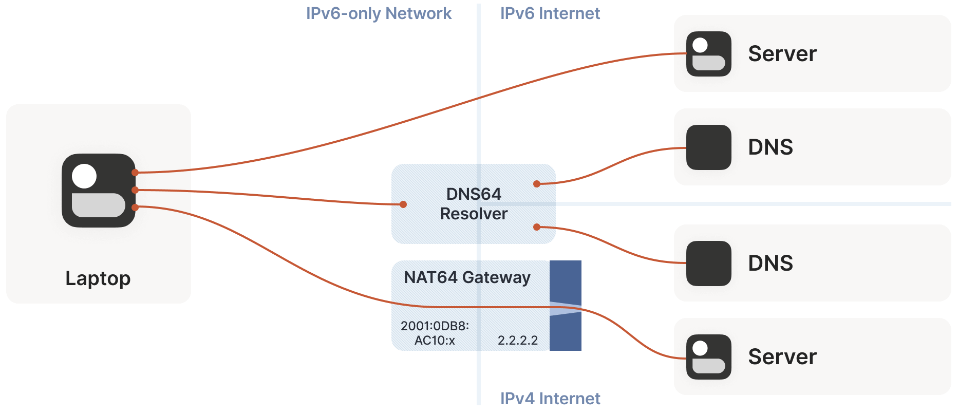
The NATs discussed earlier were NAT44 devices, converting one IPv4 address to another. NAT64, as the name suggests, converts an internal IPv6 address to an external IPv4 address. Using DNS64 devices, we can provide IPv4 DNS responses to an IPv6 network, making it appear as a fully IPv6 network to the endpoint while still accessing the IPv4 public internet.
Incidentally, you can extend this naming scheme indefinitely. There have been experiments with NAT46; you could deploy NAT66 if you enjoy chaos; and some RFCs use NAT444 for carrier-grade NAT.
This approach works well for DNS-related issues. For example, connecting to google.com involves resolving the domain to an IP address, which engages a DNS64 device, which in turn involves a NAT64 device, but the latter step is transparent to the user.
However, for NAT and firewall traversal, we care about specific IP addresses and ports.
Solution: CLAT (Customer-Side Translator)
If the device supports CLAT (Customer-Side Translator—from Customer XLAT), we’re in luck:
- CLAT pretends the operating system has a direct IPv4 connection, while using NAT64 behind the scenes, transparent to applications. On CLAT-enabled devices, we don’t need to do anything special.
- CLAT is very common on mobile devices but rare on desktops, laptops, and servers. On the latter, we must perform CLAT’s tasks: detect the presence of NAT64+DNS64 and use them correctly.
Solution: Manually Traversing NAT64 Devices Without CLAT
First, detect the presence of NAT64+DNS64.
The method is simple: send a DNS request to
ipv4only.arpa. This domain resolves to a known, fixed IPv4 address, and it’s purely IPv4. If the response is an IPv6 address, a DNS64 server performed the translation, implying the use of NAT64. This allows us to determine the NAT64 prefix.Subsequently, when sending packets to an IPv4 address, send IPv6 packets in the format
{NAT64 prefix + IPv4 address}. Similarly, packets received from a source in the format{NAT64 prefix + IPv4 address}are IPv4 traffic.Next, communicate with a STUN server through the NAT64 network to obtain our public
ip:porton the NAT64, returning to the classic NAT traversal problem—with a bit of extra work.
Fortunately, most v6-only networks today are mobile operator networks, and nearly all phones support CLAT. ISPs running v6-only networks deploy CLAT on the routers they provide, so you often don’t need to do anything. However, to achieve 100% traversal, you must address these edge cases by explicitly supporting connections from v6-only networks to v4-only peers.
7.8 Integrating All Solutions into the ICE Protocol
Which Traversal Method for Specific Scenarios?
Our NAT traversal journey is nearly complete. We’ve covered stateful firewalls, simple and advanced NATs, and IPv4 and IPv6. Implementing all the solutions above achieves the goal of NAT traversal!
However:
- For a given peer, how do we decide which method to use?
- How do we determine if it’s a simple stateful firewall scenario, one requiring the birthday paradox algorithm, or one needing manual NAT64 handling?
- Or perhaps both parties are on the same Wi-Fi network without any firewalls, requiring no action?
Early NAT traversal was simpler, allowing us to precisely identify the path characteristics between peers and apply the appropriate solution. However, network engineers and NAT device developers introduced new concepts, complicating path determination. Thus, we need to simplify the client-side decision-making (judgment logic).
This brings us to the Interactive Connectivity Establishment (ICE) protocol. Like STUN and TURN, ICE originates from the telecom industry, so its RFC is filled with terms like SIP, SDP, signaling sessions, and dialing. Ignoring these domain-specific terms, we see it describes an elegantly simple algorithm for determining the best connection path.
Really? The algorithm is: try every method and choose the best one. That’s it—surprised?
Let’s dive deeper into this algorithm.
ICE (Interactive Connectivity Establishment) Algorithm
This discussion won’t strictly adhere to the ICE specification. If implementing an interoperable ICE client, you should thoroughly read RFC 8445 and follow its guidelines. Here, we ignore telecom terminology, focusing on the core algorithm logic and offering a few flexible suggestions within the ICE specification’s allowances.
To communicate with a peer, first determine the addresses of the socket used on our (client) side. This is a list that should include at least:
- Our own IPv6
ip:ports. - Our own IPv4 LAN
ip:ports(local network addresses). - Our own IPv4 WAN
ip:portsobtained via STUN servers (public addresses, possibly translated via NAT64). - Our own IPv4 WAN
ip:portobtained via port mapping protocols (public addresses allocated by the NAT device’s port mapping protocol). - Endpoints provided by the ISP (e.g., statically configured port forwards).
- Our own IPv6
Exchange this list with the peer via a side channel. Once both sides have the other’s list, begin probing the addresses provided by the peer. The addresses in the list have no priority, meaning if the peer provides 15 addresses, we should probe all 15.
These probe packets serve two purposes:
- Open firewalls and traverse NATs, as described throughout this article.
- Health checks. We continuously exchange (preferably authenticated) “ping/pong” packets to verify if a specific path is end-to-end viable.
Finally, after a short while, select the “best” address from the available candidates (based on certain criteria), and the task is complete!
The elegance of this algorithm lies in that, as long as the algorithm for selecting the best path (address) is correct, you’ll always get the optimal path.
- ICE pre-sorts these candidate addresses (typically: LAN > WAN > WAN+NAT), but users can customize this sorting behavior.
- Starting with v0.100.0, Tailscale switched from hardcoded priorities to sorting based on round-trip latency, which generally aligns with
LAN > WAN > WAN+NAT. However, unlike static sorting, we dynamically calculate which category each path belongs to.
The ICE specification organizes the protocol into two phases:
- Probing phase
- Communication phase
However, you don’t need to strictly follow this order. At Tailscale:
- We automatically switch to a better path when discovered.
- All connections start in DERP mode (relay mode). This means connections are established immediately (the lowest-priority but 100% successful mode), with no user wait time.
- Path discovery runs in parallel. Typically, within a few seconds, we find a better path and transparently upgrade the existing connection to it.
One concern is asymmetric paths. ICE expends effort to ensure both communicating parties select the same network path, ensuring bidirectional traffic to keep firewalls and NAT devices’ connections open. When implementing yourself, you don’t need to invest as much effort in this guarantee, but you must ensure all used paths have bidirectional traffic. This is simple: periodically send ping/pong packets on all active paths.
Robustness and Downgrading
For robustness, you must detect if the currently selected path has failed (e.g., the NAT device clears all state during maintenance). If it fails, downgrade to another path. There are two approaches:
Continuously probe all paths, maintaining a list of fallback addresses for downgrading.
Directly downgrade to the fallback relay mode, then upgrade to a better path via path probing.
Given the low probability of downgrading, this approach is likely more economical.
7.9 Security
Finally, we must address security.
All content in this article assumes the upper-layer protocol has its own security mechanisms (e.g., QUIC uses TLS certificates, WireGuard has its own public keys). If no security mechanism exists, it must be added immediately. Once paths switch dynamically, IP-based security mechanisms become useless (the IP protocol wasn’t designed with security in mind), requiring at least end-to-end authentication.
- Strictly speaking, if the upper-layer protocol has security mechanisms, even deceptive ping/pong traffic isn’t a major issue. The worst case is an attacker inducing both sides to relay traffic through their system. With end-to-end security, this isn’t a significant problem (depending on your threat model).
- For caution, it’s best to authenticate and encrypt path discovery packets as well. Consult your application security engineers for specifics.
We’ve finally achieved our NAT traversal goal!
If you implement all the techniques mentioned, you’ll have industry-leading NAT traversal software capable of direct end-to-end connections in most scenarios. If direct connections fail, you can fall back to relay mode (for Tailscale, sometimes only relays are possible).
However, this is complex work! Some issues are fascinating to study but difficult to get perfectly right, especially edge cases that rarely occur but require significant effort to address. Fortunately, this work needs to be done only once. Once solved, you gain a superpower: exploring the exciting, relatively new world of end-to-end applications (peer-to-peer applications).
8.1 End-to-End Connectivity Across the Public Internet
Many intriguing ideas in the decentralized software space boil down to achieving end-to-end connectivity across the public internet. It may seem simple at first, but it’s far more challenging than imagined. Now that you know how to solve this problem, get started!
8.2 Conclusion: TL;DR
Building robust NAT traversal requires the following foundations:
- A UDP-based protocol.
- Direct access to sockets within the program.
- A side channel for communicating with peers.
- Several STUN servers.
- A fallback relay network (optional but strongly recommended).
Then, you need to:
- Iterate through all
ip:portcombinations. - Query STUN servers to obtain your public
ip:portinformation and assess the “difficulty” of your side’s NAT. - Use port mapping protocols to acquire additional public
ip:ports. - Check for NAT64 and obtain your public
ip:portthrough it. - Exchange all your public
ip:portswith the peer via the side channel, along with encryption keys to ensure communication security. - Optionally, start communication using the fallback relay mode (for quick connection establishment).
- If necessary or desired, probe all
ip:portcombinations provided by the peer and perform birthday attacks to traverse harder NATs. - Transparently upgrade to a better path when discovered.
- Downgrade to other available paths if the current path fails.
- Ensure everything is encrypted with end-to-end authentication.